


- General Presentation
- Project summary
- Project Objectives
- Team members
- List of publications
- Results
- Cognitive and socio-economic impact
Project code: PN-IV-PCB-RO-MD-2024-0188
Contract number: 57PCBROMD/2025
Project title: “Research and development of an innovative centrifugal pump design for space applications”
Acronym: REEDITED
Field of specialization: Digitalization, industry and space
Contracting Authority: Executive Agency for Higher Education, Research, Development and Innovation Funding
Project duration: 24 months (01/09/2025 – 31/08/2027)
Consortium:
CO: Romanian Research & Development Institute for Gas Turbines - COMOTI
P1: Technical University of Moldova
Project Budget:
Total budget: 599.543,00 lei
Project Director (CO): Dr. Eng. Ion MĂLĂEL
Project Responsible (P1): Dr. Eng. Andrei PETCO
The scope of the proposal is based on the research and development of a promising solution for aerospace applications. The overall objective of this project is to achieve laboratory validation of an innovative centrifugal pump concept that can replace the traditional solution. The results of the project will be used in a future research proposal aimed at using this knowledge to develop a competitive product. The proposed technology is relevant in the context of space travel and even the race to land on Mars. This goal is aligned with ESA's current objectives for the next 15 years, and the ambition of the proposal is to provide a new solution for space propulsion.
Specific objectives to be achieved within the project REEDITED are:
- OS 1 - defining a new configuration of the centrifugal pump concept;
- OS 2 - definition/selection of the optimal technical solution for the centrifugal pump;
- OS 3 - manufacturing a small-scale experimental model using the research infrastructure belonging to the consortium partners;
- OS 4 - development of a new testing procedure for the experimental campaign of the entire system;
- OS 5 - increasing international visibility by publishing high-quality scientific papers in prestigious journals and participating in competitive research programs.
Each specific technical objective mentioned above is relevant to the project outcome as it reflects an important phase required for the validation of the proposed demonstrator. All defined objectives are realistically achievable and the project is feasible, given the consortium's experience in the field of numerical optimization/centrifugal pumps/ and the infrastructure of both entities involved, as well as the need for new solutions in the industry.
| Partner | First name Last name | Role in the project | Cod UEF-ID Brainmap |
|---|---|---|---|
| CO - COMOTI - Romanian Research & Development Institute for Gas Turbines | Ion MĂLĂEL | Project Director | U-1700-038N-5215 |
| Theodora ANDREESCU | Doctoral Member | U-1700-037Z-9800 | |
| Mihaela Raluca CONDRUZ | Researcher Member | U-1700-037K-8990 | |
| George Bogdan GHERMAN | Researcher Member | U-1800-046R-6635 | |
| Andreea ALCEA | Doctoral Member | U-1800-055R-1514 | |
| Alexandru-Claudiu CĂNCESCU | Postdoctoral Researcher Member | U-1900-064A-6855 | |
| P1 - Technical University of Moldova | Andrei PETCO | Partner Manager | U-2300-070K-1006 |
| Marin GUȚU | Researcher Member | U-1900-063U-2991 | |
| Andrei GHEORGHIȚĂ | Researcher Member | U-2300-070S-1138 | |
| Viorel BOSTAN | Researcher Member | U-2400-071W-7687 |
Preliminary results:
The flow in a new centrifugal pump design was investigated using the numerical simulation with the two-equation SST turbulence model. A comparison between this new pump design and a classical two-stage centrifugal pump was performed in previous research. To prepare the geometries for numerical simulations, for both cases, the computational domain was created using an automatic block-structured discretization system dedicated to rotating machine configurations. In the process of grid generation, its quality was taken into account, in terms of orthogonality and cell aspect ratio. The generated grids for rotor 1, rotor 2 and stator are illustrated in figure 1.
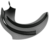
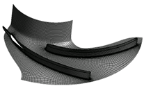
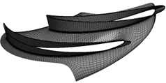
a) Rotor 1 b) Rotor 2 c) Stator
Figure 1. Centrifugal pump component grids
The target for the final grid size was approximately 1.5 million cells for all domains, with 30 total number of vanes. The first cell size was defined to achieve the unity value for y+ at the first point away from solid walls.
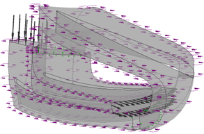
Regarding the configuration of the two cases investigated, using both discussed geometries, at the inlet, the total pressure p_in = 20 bar was set to avoid problems related to the cavitation phenomenon. Usually, an inductor can be used to achieve this pressure, but in this research, only the rotor and stator side were investigated and we assume that, in each case, the output pressure from the inductor is 20 bar. At the pump outlet, the mass flow rate for all sectors was imposed, Q̇ = 40.4 kg/s, and a monitoring point at the inlet was set with this variable to verify the convergence of the numerical solution.
The walls (vanes, hub and housing) use the free slip condition, and the moving reference frame model is assigned a rotational speed of 36,000 RPM around the Z axis. The boundary conditions, for each case, are illustrated in figure 2.
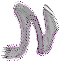
a) Classical configuration b) New configuration
Figure 2. Boundary conditions
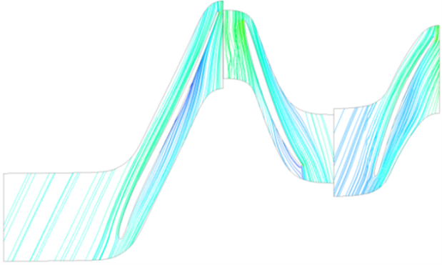
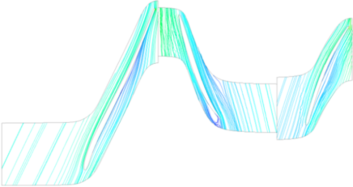
A comparative study between a classic pump configuration and a new design proposed in the project was carried out to evaluate their performances. Figure 3 shows the streamlines for both cases at a 50% vane height. No recirculation zones are developed that can influence the pump performances, as can be seen.
a) Classical configuration b) New configuration
Figure 3. Streamlines
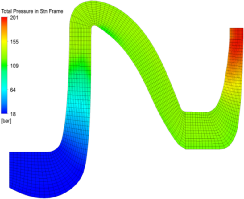
To evaluate the pressure evolution within the STN, a meridional view was used to observe the graph on an axial-radial plane. Figure 4 shows the meridional graphs for the pumps studied using the circumferential averaging option by mass flow, where the total pressure value within the STN at each sampling point is calculated as an average of the mass flow on the corresponding circular band.
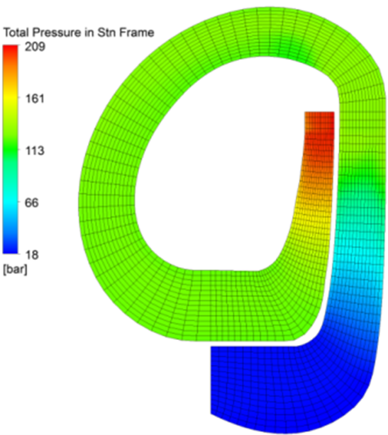
a) Classical configuration b) New configuration
Figure 4. Total Pressure
For both investigated geometries, the outlet pressure values are slightly similar, as can be seen in the two previous images. In addition, the overall efficiency of the analyzed configurations was approximately 97% for both. The advantage of the proposed geometry is that it reduces the total axial length of the pump by 60% compared to the classic two-stage configuration, without reducing its performance.
STAGE I:
SCIENTIFIC REPORT
Project Title:
“Research and Development of an Innovative Centrifugal Pump Design for Space Applications”
- Contract no. 57PCBROMD/2025
- Phase no. 1/2025
Project Director,
Senior Researcher I, PhD Eng. Ion MĂLĂEL
Scientific description highlighting the results of the annual stage and the degree of achievement of the objectives
Abstract
This paper represents the deliverable of Phase I of the project "Research and Development of an Innovative Centrifugal Pump Design for Space Applications", funded through the National Plan for Research, Development and Innovation 2022–2027, PNCDI IV, 5.8 – European and international cooperation program, 5.8.3 – Bilateral/multilateral subprogram, complex bilateral projects with the Republic of Moldova, competition identifier: PN-IV-PCB-RO-MD-2024-0188.
The study presents the modeling and numerical analysis of a two-stage centrifugal pump, using SolidWorks for geometry generation and ANSYS CFX for performance evaluation. The rotor–stator geometry was built parametrically, including blade definition using Loft features and the configuration of the fluid domain required for simulation.
The results validate the numerical model and establish the comparison basis for the optimized geometry to be analyzed.
Introduction
Centrifugal pumps represent essential equipment in fluid engineering, being widely used in various industries such as water supply, chemical, energy, or petrochemical industries. Their operation is based on the conversion of mechanical energy supplied by the rotor into an increase in pressure and velocity of the fluid. The efficiency and hydraulic performance of pumps depend on the geometric parameters of the rotor, casing, and blades, as well as on operating conditions.
In recent decades, the development of digital design and simulation technologies has radically changed the way industrial equipment is conceived and analyzed. The evolution of computer-aided design (CAD) and computational fluid dynamics (CFD) analyses has enabled a much more detailed understanding of the behavior of these hydraulic machines, largely eliminating the need for costly experimental testing.
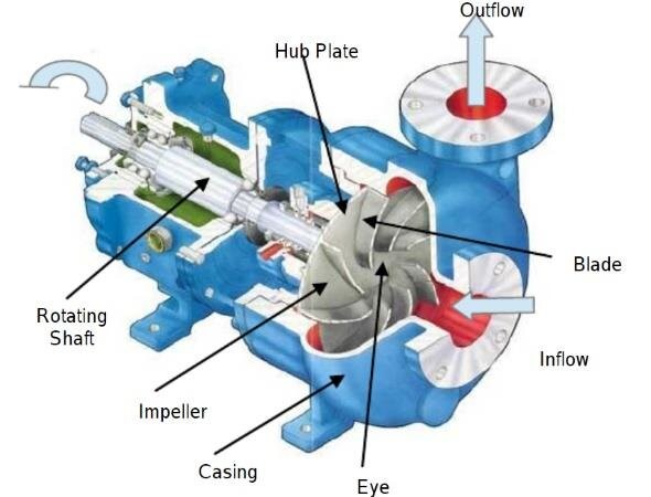
Figure 1 – Conceptual scheme of a standard centrifugal pump
SolidWorks and ANSYS CFX are today two of the most widely used tools in this field. The former provides a robust three-dimensional modelling environment capable of accurately describing the complex geometry of a centrifugal pump, while the latter allows detailed analysis of internal flows, pressure distribution, and hydraulic losses. Recent studies in the literature show that integrating the two platforms significantly contributes to optimizing hydraulic performance, reducing energy consumption, and improving the durability of the mechanical assembly.
The first studies dedicated to the application of CFD methods in the analysis of centrifugal pumps appeared in the 1990s, but their truly significant development occurred after 2005, with the increase in computational power and the refinement of turbulence models. El-Emam, M. A. and collaborators (2022) provided one of the first comprehensive reviews on the development stage of numerical simulations for centrifugal pumps, highlighting the extremely complex nature of three-dimensional flows within them.
They showed that turbulence, recirculation effects, and the interaction between blades and the casing volute generate nonlinear velocity and pressure distributions that cannot be described by classical analytical methods. This type of analysis opened the way toward full integration of design and optimization stages using digital tools.
CAD modelling represents the essential starting point. SolidWorks, widely used in both academic and industrial environments, offers the capability to accurately model each component of the pump — from the rotor to the volute and the suction and discharge pipes.
In recent works, emphasis has been placed on obtaining a geometric representation that faithfully reflects the fluid flow and can be transferred without errors to the CFD analysis environment. The study by Cenci, G. and collaborators (2006) describes the process of designing an impeller in SolidWorks and the subsequent analysis in ANSYS CFX, aiming to optimize the blade angle to increase overall efficiency.
The authors showed that small modifications in the blade exit angle can lead to considerable variations in static pressure and pump flow rate, demonstrating the high sensitivity of the system to geometric parameters.
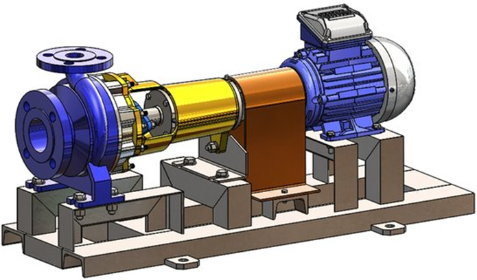
Figure 2 – CAD model of the pump created in SolidWorks
The CAD modelling process is not limited to the construction of the solid volume. In order to perform a correct CFD analysis, the researcher must generate the so-called fluid domain, meaning the volume actually occupied by the liquid during pump operation.
This involves defining internal surfaces, cleaning the geometry of unnecessary details, and preparing a model that can be efficiently discretized. Any imperfection at this stage can lead to major numerical errors in CFD simulation.
SolidWorks offers the advantage of an intuitive interface and the possibility of exporting in standard formats (STEP, IGES) compatible with ANSYS Workbench, facilitating a clean transfer of the model between the two platforms.
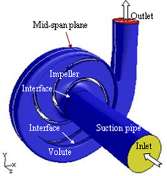
Figure 3 – Fluid domain generated for CFD analysis
After completing the geometry, CFD analysis in ANSYS CFX becomes the critical step in understanding pump behavior. This software is recognized for its accuracy in solving the Navier–Stokes equations for incompressible or compressible fluids, in steady or transient regimes. Pedersen, N. and collaborators (2003), for example, used ANSYS CFX to simulate the flow in a radial pump, comparing numerical results with experimental measurements obtained through Particle Image Velocimetry (PIV). Their results confirmed that CFD simulation can accurately reproduce velocity and pressure distributions inside the pump, with errors below 5%, validating the method as a design tool.
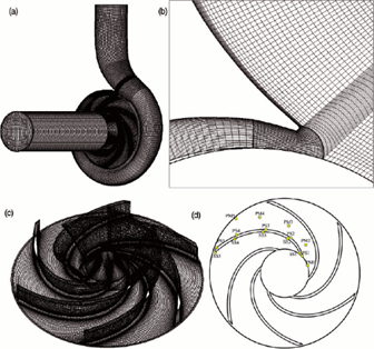
Figure 4 – Discretization mesh generated for simulation
An essential aspect highlighted in the literature is the influence of the turbulence model on simulation accuracy. The k–ε and k–ω SST models are the most commonly used, each having specific advantages and limitations.
The k–ε model, for example, is stable and fast, but tends to underestimate velocity gradients near walls. In contrast, the k–ω SST model provides a more accurate prediction of flow in the boundary layer, but is more sensitive to boundary conditions.
The choice of the appropriate model depends on the purpose of the study and the level of detail required. In general, for standard centrifugal pumps, the k–ω SST combination has become preferred due to the balance between accuracy and numerical stability.
Once boundary conditions are established and the mesh is generated, the simulation can provide a complete picture of velocity and pressure fields. Thus, researchers can observe recirculation zones behind blades, low-pressure regions susceptible to cavitation, or flow variations in the casing volute.
The study by Derakhshan et al. (2013) mentions that the impeller is the component with the greatest influence on the overall performance of the pump, and its optimization through CFD can lead to efficiency increases of up to 10%. This finding confirms the importance of numerical analysis as a geometric optimization tool.
Another relevant example is the study by Bellary, S. A. I., and Samad, A. (2014), who conducted a parametric study on impeller geometry, varying the blade exit angle and the trailing edge shape.
Their results showed that small adjustments of these parameters can lead to significant improvements in hydraulic efficiency. In addition, it was observed that the volute shape plays a crucial role in converting kinetic energy into pressure energy, and mismatches between the volute cross-sections and the flow direction can generate additional losses.
The integration between CAD and CFD represents, beyond the technical aspect, a paradigm shift in the engineering design process. If in the past CAD models were viewed only as geometric representations, today they become “intelligent” models, directly connected to performance analyses.
When a designer modifies a rotor dimension in SolidWorks, the effect can be observed almost instantly in the CFD simulation, due to the bidirectional interface between the two applications. This integrated approach allows rapid development of multiple design versions and the selection of the optimal one based on multiple criteria, such as efficiency, cost, and dynamic stability.
A concrete example of applying this methodology is provided by the research team led by Faisal, A. R. (2021), who combined CFD analysis with structural analysis using the finite element method (FEM) for a standard centrifugal pump.
They used SolidWorks for 3D modelling, ANSYS CFX for hydrodynamic simulation, and ANSYS Mechanical for evaluating structural stresses on the blades. Their study demonstrates the benefit of integrating geometric modelling, fluid analysis, and mechanical analysis, resulting in a complete understanding of system behavior.
This hybrid approach is increasingly encountered in the literature and reflects the current trend of treating the centrifugal pump not only as a hydraulic system, but as a complex fluid–structure assembly.
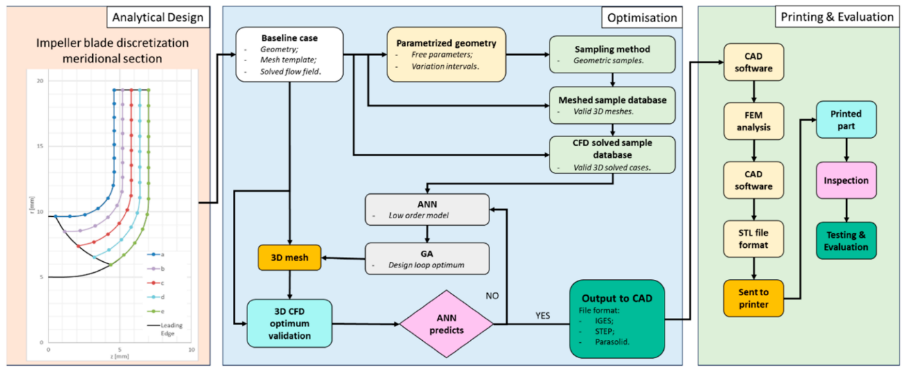
Figure 5 – Velocity (a) and pressure (b) distribution in the mid-section of the pump
The evolution of software, the increase in computational capacity, and the growing accessibility of these technologies open wide possibilities for researchers and engineers. Currently, a complete pump model can be built and virtually tested in just a few hours, a process that previously required weeks of design and physical testing. Moreover, CFD simulations provide information impossible to obtain through direct measurements — for example, pressure distribution on each blade surface or local fluid velocity in the corners of the volute.
The literature analysis also suggests several future research directions. One of these is the use of artificial intelligence and genetic algorithms for automatic optimization of impeller geometry. Parametrically generated CAD models can be automatically modified according to defined objectives (for example, maximizing efficiency or minimizing losses), and CFD simulations can evaluate the performance of each variant. This iterative loop, supported by high-speed computing, promises to revolutionize pump design. Additionally, combining CFD with vibration and noise analysis opens new perspectives on acoustic comfort and equipment durability.
The present report aims to document the CAD modeling process of a centrifugal pump using SolidWorks and the CFD analysis of the initial geometry in ANSYS CFX, in order to determine hydraulic performance such as flow rate, head, and efficiency.
Thus, the report will detail both the stages of CAD model construction, as well as the preparation and execution of CFD simulations, interpretation of results, and discussion of the hydraulic performance of the initial geometry.
CAD modeling of the centrifugal pump
Centrifugal pumps operate based on the principle of transforming the mechanical energy of the impeller into kinetic energy and pressure of the fluid. The fluid enters the impeller axially and is accelerated radially by the motion of the blades, exiting into the casing with increased velocity. The kinetic energy of the fluid is then converted into pressure through the casing and diffuser, according to the Bernoulli equation:
P+1/2 ρv^2+ρgh="constant" (1)
The hydraulic efficiency of the pump is given by the relation:
η_h=ρgQH/P_mec (2)
A standard centrifugal pump includes the following elements:
- impeller – the rotating component that imparts velocity to the fluid. Types of impellers include: open, semi-open, and closed;
- casing – collects the fluid from the impeller and directs the flow toward the outlet. The volute shape helps convert velocity into pressure;
- blades – their profile and angle determine flow rate and head characteristics;
- shaft – transmits torque from the motor to the impeller, supported by bearings;
- seals and gaskets – prevent fluid leakage and the ingress of impurities.
The main parameters defining the performance of a centrifugal pump are: Volumetric flow rate (Q) – the amount of fluid pumped per unit time; Head (H) – the total energy difference between inlet and outlet, expressed in meters; Efficiency (η) – the ratio between useful energy transferred to the fluid and mechanical energy absorbed by the impeller; NPSH (Net Positive Suction Head) – an indicator of cavitation risk.
Centrifugal pumps can be classified according to several criteria: impeller geometry: radial, semi-axial, axial; number of stages: single-stage or multi-stage; operating conditions: for clean liquids, viscous liquids, or suspensions. Their application fields include: water supply, chemical and petrochemical industry, energy generation, HVAC, and industrial cooling systems.
For this study, a standard two-stage centrifugal pump with closed impellers was selected, used in general industrial applications. The main geometric parameters are presented in the table below.
Table 1 – Geometric parameters for the initial pump
| Parameter | Value | Unit |
|---|---|---|
| Impeller diameter (D) | 155 | mm |
| Number of blades | 6 | - |
| Blade type | backward-curved | - |
| Rotational speed (n) | 2950 | rpm |
| Nominal flow rate (Q) | 130 | m3/h |
| Head (H) | 20 | m |
The computer-aided three-dimensional modeling was carried out using the SolidWorks 2024 platform, with the main purpose of generating and rigorously defining the flow domains required for the subsequent stages of numerical simulation in ANSYS CFX. The modeling process included the construction of the functional geometry of the internal pump components, the definition of fluid boundaries, as well as the creation of surfaces and volumes to be discretized for CFD analysis. This preliminary stage is essential, as the accuracy of the flow domains directly influences the quality of the numerical solutions and the reliability of the conclusions obtained during the simulation phase.
Within this first stage, a detailed evaluation of the performance of the classical two-stage centrifugal pump configuration was pursued, considered as the benchmark for the present study. This conventional solution was analyzed from the perspective of its hydraulic characteristics, fluid dynamic behavior, and overall efficiency, in order to establish a solid and objective comparison baseline. The results obtained from the simulation of the traditional pump will subsequently serve as a reference against which the new pump concept developed in this project will be investigated and validated, allowing the highlighting of performance improvements, identification of constructive advantages, and confirmation of the technological benefits that the new geometry may provide.
The CAD modeling process of the two-stage centrifugal pump in SolidWorks was structured in such a way as to allow the clear definition of the three main components – the first-stage impeller, the stator acting as an intermediate guiding element, and the second-stage impeller. At this stage, the final volute was not modelled, as the focus was placed on developing the internal hydraulic block required for analyzing the flow between stages.
The modeling began with the construction of the skeleton of the first-stage impeller, by defining the characteristic diameters and blade thickness, fundamental elements for establishing the hydraulic architecture. Once the geometric layout was defined, the number of blades was configured using the Circular Pattern function, ensuring uniform distribution around the rotation axis and maintaining functional symmetry. The same principle was subsequently applied to the second-stage impeller in order to maintain geometric consistency between the two stages.
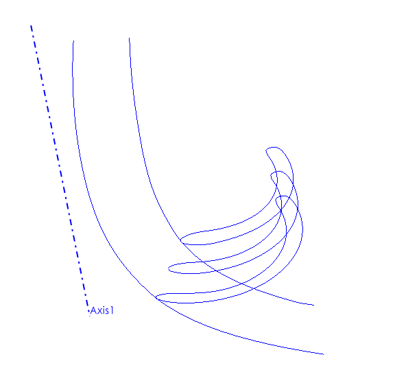
Figure 7 – First-stage impeller skeleton
After establishing the initial geometry of the impellers, the process focused on modeling the blade profile. These were defined in a sectional plane, respecting the hydraulic inlet and outlet angles (β₁ and β₂) specific to each pump stage. In order to obtain a continuous surface without discontinuities and with curvature optimized for flow, the Loft function was used to generate the three-dimensional blade shapes. This approach ensures a smooth transition of the fluid flow between the inlet and outlet regions of the impeller, which is essential especially in multi-stage pumps, where disturbances from the first stage can influence the operation of the second stage
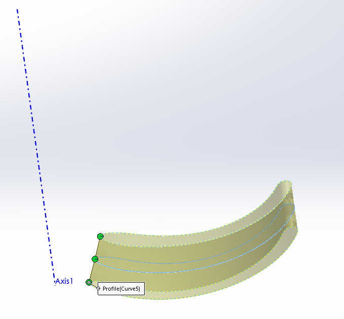
Figure 8 – Blade profile (Loft)
The next stage consisted of modeling the stator, the intermediate component responsible for partially converting kinetic energy into pressure energy and redirecting the flow toward the next impeller. The stator was designed based on trajectories defined for the guide vanes, having the role of realigning the flow direction after exiting the first impeller. Its geometry was created to minimize turbulence and hydraulic losses, providing optimal conditions for feeding the second-stage impeller.
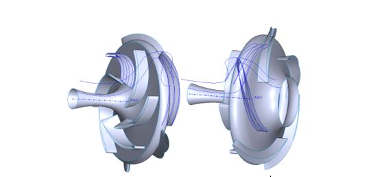
Figure 9 – First-stage impeller + stator
Once the main components were completed, the assembly process took place, combining the first-stage impeller, stator, and second-stage impeller into a common coaxial configuration. The positioning of each element was performed while respecting the functional clearances specific to closed centrifugal pumps, maintaining lateral and axial gaps in the range of approximately 1–2 mm. At this stage, checks were performed using the Interference Detection function to identify possible overlaps or collisions between moving and stationary components, ensuring correct geometric operation of the assembly.
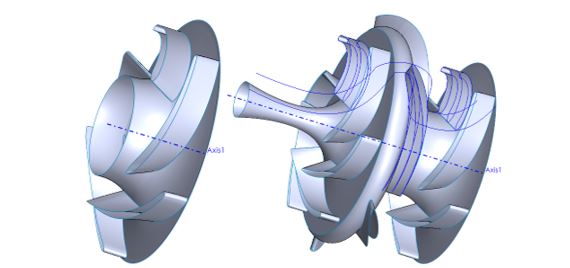
Figure 10 – Second-stage impeller and final assembly
Finally, the entire geometry was subjected to a Check Geometry analysis to identify topological errors, unclosed edges, or defective surfaces that could compromise the CFD simulation stage. After full validation of the model, the assembly was exported in STEP format, prepared for use in ANSYS CFX, where the flow behavior inside the pump was to be analyzed, with emphasis on the fluid interaction between the two stages.
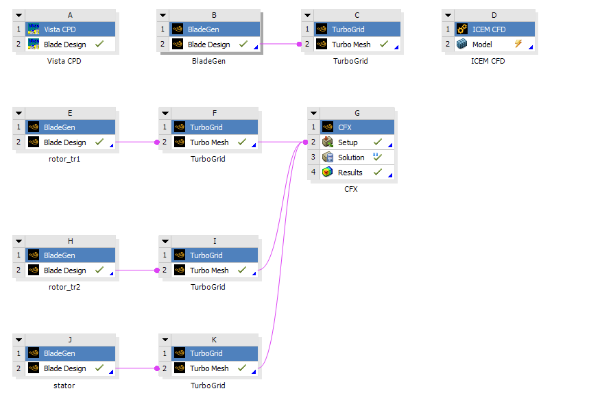
Figure 11 – Flow between stages, schematic from Workbench platform
Performing the CFD numerical calculation for determining the performance of the initial geometry
The Reynolds-Averaged Navier-Stokes (RANS) formulations together with the corresponding turbulence models are very useful especially for the “rapid screening” of a large number of cases or configurations in Computational Fluid Dynamics (CFD). The steady-state RANS technique is the preferred method in industry for analyzing turbulent flows due to the large number of configurations that can be simulated in a short period of time, identifying trends in flow behavior.
Within the RANS method, two-equation turbulence models are the most widely used. The most popular two-equation model is the standard k–ε model, which is robust, fast, and provides reasonable accuracy for a wide range of turbulent flows. Another two-equation model is the standard k–ω turbulence model, based on Wilcox’s k–ω formulation with two transport equations for k and the specific dissipation rate (ω).
An improved turbulence model is the SST k–ω model:
█(∂k/∂t+u ̅ ∂k/∂x+v ̅ ∂k/∂x+w ̅ ∂k/∂x=@=Γ_k ((∂^2 k)/(∂x^2 )+(∂^2 k)/(∂y^2 )+(∂^2 k)/(∂z^2 ))+G ̃_k-Y_k@∂ω/∂t+u ̅ ∂ω/∂x+v ̅ ∂ω/∂x+w ̅ ∂ω/∂x=@=Γ_ω ((∂^2 ω)/(∂x^2 )+(∂^2 ω)/(∂y^2 )+(∂^2 ω)/(∂z^2 ))+G_ω-Y_ω+D_ω ) (3)
Using the commercial CFX solver (ANSYS, Inc.), the two-equation turbulence model (SST k–ω) was employed to investigate the flow in a classical two-stage centrifugal pump design. The geometry of this case is presented in the figure below.
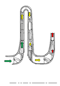
Figure 12 – Cross-section of the centrifugal pump for a classical two-stage configuration
The green arrows represent the inlet of the centrifugal pump, while the red arrows represent the outlet. In this case, the computational domain was created using TURBOGRID software, which is an automatic structured block mesh generation system dedicated to turbomachinery configurations. During the mesh generation process, grid quality was monitored in terms of orthogonality, expansion ratio, and cell aspect ratio. The figure below presents the meshes for the first impeller, stator, and second impeller.
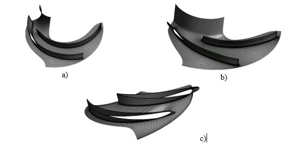
Figure 13 – Mesh: a) impeller 1; b) impeller 2; c) stator
The target for the final mesh size was approximately 1.8 million cells for all domains, with a number of elements along the blade height of 50. The first near-wall cell size was defined to achieve a y+ value on the order of unity at the first point away from solid walls.
At the inlet, the total pressure was set to pin = 1 atm, while at the outlet, the mass flow rate was imposed for all sectors, Q̇ = 36.11 kg/s, and a monitoring point was set at the inlet with this variable to verify convergence of the numerical solution.
The walls (blades, hub, and casing) were defined with slip condition, and a rotational speed of 2950 RPM around the Z axis was imposed. Turbulence at the inlet and outlet was set to a medium intensity equal to 5%.
The boundary conditions for this case are presented in Figure 14.
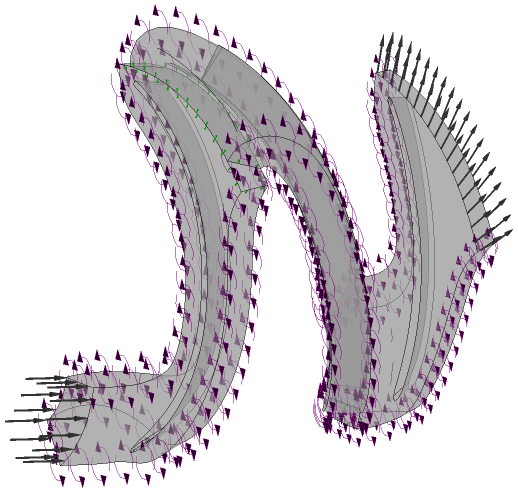
Figure 14 – Boundary condition setup
A three-dimensional CFD analysis was performed on a single passage using water as the working fluid. The results of this numerical investigation will be used in a comparative study between the classical pump configuration and the new design developed within this research project.
Figure 15 presents the streamlines in a blade-to-blade view at 50% of the blade height. It can be observed that no recirculation zones are developed that could influence pump performance.
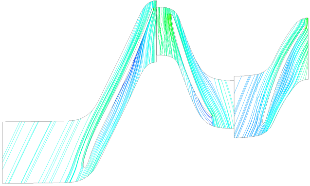
Figure 15 – Streamlines at 50% of blade height
To evaluate the evolution of the total pressure in Stn, a meridional view was used to observe the plot on an axial–radial plane. Figure 16 presents a meridional view for the studied pump using the circumferential averaging option by mass flow rate, where the value of the total pressure in Stn at each sampling point is calculated as a mass-flow-weighted average over the corresponding circular band.
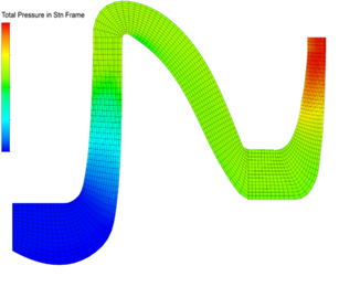
Figure 16 – Total pressure in Stn, meridional view
The analysis of the total pressure variation obtained through CFD simulation in ANSYS CFX confirms the proper operation of the two-stage centrifugal pump, highlighting two distinct pressure increases characteristic of each rotor–diffuser stage. The total pressure increases progressively from inlet to outlet, with significant jumps in the regions corresponding to the stages, followed by short stabilization sections between them. The final pressure value at discharge remains nearly constant, indicating a stable flow regime and efficient conversion of kinetic energy into pressure energy. The results confirm the consistency of the pressure distribution with the operating principles of multistage pumps and support the validity of the numerical model used.
Figure 17 presents the variation of total pressure along the flow direction, from inlet to outlet, in a classical two-stage centrifugal pump analyzed through CFD simulation using ANSYS CFX. The vertical axis represents total pressure, while the horizontal axis represents the streamwise position corresponding to the fluid path through the pump.
The pressure distribution highlights the characteristic behavior of a multistage pump:
- Inlet region (0 – ~0.4) The pressure remains almost constant, at a relatively low value, representing the hydraulic conditions in the inlet diffuser. No significant pressure increase is observed, indicating stable flow before entering the first-stage impeller.
- Pressure increases in the first stage (0.4 – ~1.0) In this region, a rapid and substantial increase in total pressure occurs, corresponding to the conversion of kinetic energy into pressure energy within the first-stage impeller and its associated diffuser. This pressure rise is typical for high-efficiency radial stages.
- Inter-stage / stabilization region (1.0 – ~2.0) After the diffuser of the first stage, the pressure oscillates, with a slight downward trend. This region usually corresponds to the intermediate zone between stages, where losses due to recirculation or local velocity redistribution may occur.
- Pressure increases in the second stage (2.0 – ~2.8) The graph shows a second major increase in total pressure. This reflects the operation of the second-stage impeller and the reconversion of hydraulic energy.
- Discharge region (2.8 – 3.1) The total pressure stabilizes around maximum values, indicating the final regime at the pump outlet and confirming the cumulative effect of the two stages.
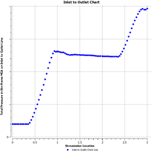
Figure 17 – Total pressure variation from inlet to outlet
Conclusions
The conducted study had as its main objective the evaluation of the hydraulic performance of a two-stage centrifugal pump through the integration of CAD modeling in SolidWorks and CFD numerical simulation in ANSYS CFX. The performed analysis confirmed the importance of using modern digital tools in the design and optimization of turbomachinery, demonstrating that the CAD–CFD approach provides a detailed and accurate picture of internal flow behavior, inaccessible through classical experimental methods.
The three-dimensional modeling performed in SolidWorks allowed obtaining a rigorous geometry for the key components — the first-stage impeller, the intermediate stator, and the second-stage impeller — as well as the correct definition of the fluid domain required for simulation. Geometry validation and interference control ensured compatibility with the ANSYS CFX numerical environment, contributing to the generation of a high-quality discretization mesh with approximately 1.8 million cells and parameters suitable for turbulent flows in turbomachinery.
The CFD simulations carried out using the SST k–ω turbulence model highlighted a stable flow regime, without significant recirculation zones, confirming the proper design of the hydraulic channels. The evolution of total pressure along the flow direction indicates two distinct increases corresponding to the efficient operation of each rotor–stator stage.
Overall, the analyzed numerical model demonstrates that the classical two-stage centrifugal pump geometry exhibits robust hydraulic behavior, with velocity and pressure distributions consistent with theoretical principles and literature data. This study establishes a solid basis for comparison with the new design proposed in the project, the results obtained here serving as a benchmark for evaluating efficiency improvements, loss reduction, and flow optimization in future configurations.
By integrating CAD and CFD stages, the report confirms the value of modern digital processes in the development of hydraulic equipment, providing a fast, reliable, and efficient tool for the design, optimization, and validation of centrifugal pumps.
Summary of progress
By implementing Phase 1 of the project “Research and Development of an Innovative Centrifugal Pump Design for Space Applications”, the partial deliverable provided in the work plan was achieved. In this regard, the following activities were carried out:
- T1.1 – Design of the innovative pump concept;
- T1.2 – Optimization of the model using neural networks and genetic algorithms (GA);
- T4.1 – Project management;
- T4.2 – Dissemination activities.
Regarding the achievement of indicators, it is noted that during the period 20.10.2025 – 03.11.2025, a team of researchers from the Republic of Moldova carried out a visit to the headquarters of the National Research and Development Institute for Gas Turbines – COMOTI, in Bucharest, Romania.
The team of the Technical University of Moldova consisted of:
- Andrei PETCO, Scientific Researcher Grade II
- Marin GUȚU, Scientific Researcher Grade II
- Andrei GHEORGHIȚĂ, Scientific Researcher Grade III
The main purpose of this visit was to establish the initial geometric parameters of the centrifugal pump and to initiate the design process. During the internship, extensive knowledge transfer activities took place regarding the use of software tools and the methodology for preliminary sizing of pump components, according to the practices of COMOTI specialists.
The software tools used include:
- SolidWorks, for 3D modeling of components,
- ANSYS CFD, for numerical flow analysis and determination of hydraulic performance of pump configurations.
Starting from the initial preliminary sizing, point files (XYZ format) describing the geometry of rotor and stator components were generated. These files were subsequently imported into the 3D modeling software to define the flow channel.
For mesh generation, ANSYS Turbogrid was used, and boundary conditions were defined in ANSYS CFX. At the end of the internship, a numerical simulation of the flow through the initial configuration of the two-stage centrifugal pump was performed, consisting of the first-stage impeller, intermediate stator, and second-stage impeller.
As part of the dissemination activities of this phase, the project website was developed and published, available at the address:
Executive summary of the activities carried out during the implementation period (max. 1 page)
The paper presents the results of Phase I of the project “Research and Development of an Innovative Centrifugal Pump Design for Space Applications”. The study analyzes the hydraulic performance of a two-stage centrifugal pump using an integrated CAD–CFD approach based on three-dimensional modeling in SolidWorks and numerical simulation in ANSYS CFX.
Centrifugal pumps, essential in industrial applications such as water supply, energy, and petrochemicals, operate based on the conversion of mechanical energy of the impeller into pressure and kinetic energy of the fluid. Their performance depends significantly on the geometry of the impeller, blades, and volute, and the development of digital technologies has enabled detailed investigation of internal flows that cannot be captured through analytical methods.
SolidWorks was used for complete modeling of the pump geometry, including the first-stage impeller, intermediate stator, and second-stage impeller. For each component, functional dimensions, hydraulic angles, and blade profiles were defined using specific features such as Loft and Circular Pattern. The resulting model was verified to eliminate intersections or discontinuities, ensuring compatibility with the simulation stage. Subsequently, the geometry was exported in STEP format for generating the flow domains in ANSYS Workbench.
The CFD analysis was performed in CFX using RANS formulations and the SST k–ω turbulence model, selected for its balance between accuracy and stability in predicting turbulent flows in turbomachinery. The fluid domain was discretized in TURBOGRID, generating a mesh of approximately 1.8 million cells, with a sufficient number of elements along blade height and an appropriate y+ value in the near-wall region. Boundary conditions included total pressure at inlet, mass flow rate at outlet, and a rotational speed of 2950 rpm imposed on the impellers, while walls were treated with slip condition.
Simulation results indicated stable flow without significant recirculation zones, demonstrating correct geometric design. Streamlines and meridional pressure distributions confirmed proper operation of both stages. The analysis of total pressure variation along the flow direction revealed two distinct increases, typical of multistage pumps: a first pressure rise in the first-stage impeller, followed by an inter-stage transition zone, then a second increase in the second stage. Pressure stabilization in the discharge region indicates a robust and efficient hydraulic regime.
The study confirms that integrating CAD and CFD stages allows obtaining an accurate picture of the internal behavior of centrifugal pumps, significantly reducing the need for physical testing and providing a rapid geometric optimization tool. The analyzed classical model constitutes a solid reference for evaluating the future design proposed in the project, offering relevant data on pressure distribution, fluid velocity, and hydraulic efficiency. The adopted digital approach demonstrates the potential of modern design methods for increasing efficiency and reducing hydraulic losses in turbomachinery.
STAGE II:
STAGE III:
STAGE I:
Cognitive Impact
The present research makes a substantial contribution to the development of knowledge in the field of turbomachinery and computational fluid dynamics, particularly through the application of integrated CAD–CFD methodologies to centrifugal pump design. By combining SolidWorks modeling with ANSYS CFX simulations, the study supports a modern, interdisciplinary engineering approach that enhances the understanding of complex internal flow phenomena, including turbulence, pressure variation, and stage interaction within multistage pumps. This approach not only deepens theoretical comprehension but also strengthens the ability to interpret nonlinear fluid behavior that cannot be captured through classical analytical methods.
At the same time, the project contributes to the development of advanced technical competencies among researchers and engineers involved in its implementation. The use of high-level numerical tools and turbulence models fosters skills in numerical simulation, parametric design, and performance evaluation, which are essential in engineering practice. Furthermore, the collaboration between research teams from Romania and the Republic of Moldova facilitated an effective transfer of knowledge, methodologies, and practical expertise, contributing to the formation of highly qualified human resources in fluid engineering. This exchange of expertise not only enhances individual competencies but also strengthens institutional research capacity.
In addition, the research promotes a shift toward simulation-driven design paradigms, where numeric models become central tools for prediction and optimization. This transition encourages analytical thinking, rapid prototyping, and innovation, reducing dependence on traditional experimental methods. The study also opens perspectives for future developments, particularly through the potential integration of artificial intelligence and optimization algorithms, which could further automate and improve the design process of centrifugal pumps.
Socio-Economic Impact
The socio-economic impact of the research is significant, particularly in the context of energy efficiency, technological innovation, and industrial development. By focusing on the optimization of centrifugal pump geometry and hydraulic performance, the study contributes to reducing energy consumption in industrial applications. Even modest improvements in pump efficiency can lead to considerable cost savings over time, especially in sectors where such equipment operates continuously, such as energy production, water supply, and petrochemical processing. This directly translates into both economic benefits and reduced environmental impact.
Moreover, the development of an innovative centrifugal pump design for space applications places the research within a high-value technological domain, supporting the advancement of aerospace engineering and related industries. The methodologies and results obtained are not limited to space applications but can be transferred to a wide range of industrial systems, enhancing the competitiveness of companies and research institutions involved in pump design and fluid machinery. The use of numeric simulation tools also reduces the need for extensive experimental testing, significantly lowering development costs and shortening the time required to bring new technologies to implementation.
Another important dimension of the socio-economic impact is the strengthening of international collaboration. The partnership between Romanian and Moldovan institutions contributes to regional integration in research and innovation, facilitating the exchange of expertise and promoting joint technological development. This collaboration not only enhances scientific output but also supports the creation of a sustainable innovation ecosystem.
Finally, the research aligns with broader sustainability objectives by enabling the design of more efficient hydraulic systems, which contribute to reduced energy consumption and lower emissions. In this context, the project supports both economic growth and environmental responsibility, demonstrating the relevance of advanced engineering research in addressing current global challenges.